Conical Disc Springs
This page introduces the Conical Disc Spring conforming to the DIN-EN 16983 standard (ex DIN2093)) - if you have a query or concern, please don´t hesitate to contact us.
The German DIN standard, (Deutches Institut fur Normung) has integrated at the European and International levels. Their standards committees aligned German interests with those of CEN and ISO. Thus the DIN 2093 has been incorporated into a European standard. There has been no substantive change.
Conical Disc Spring - Groups and Classifications
Disc Springs are conically formed angular discs, which are loaded in the axial direction. They can be used as a single disc or arranged in stacks. A Disc Spring stack can consist of disc springs arranged in either Series or Parallel sets, and we cover this briefly below. The standard divides or classifies disc springs into 3 groups as given in the table:
* - this is one of our areas of specialty
Series
Within each Group there are three dimensional Series — A, B, and C. These series are differentiated by material thicknesses and the corresponding Load Characteristic Curves or force/deflection curves they will generate, as illustrated in the accompanying diagram.
DIN EN 16983 (formerly DIN 2093) categorizes the three series by the following approximate ratios:
- Series A where De/t ≈ 18 and ho/t ≈ 0.4
- Series B where De/t ≈ 28 and ho/t ≈ 0.75
- Series C where De/t ≈ 40 and ho/t ≈ 1.3
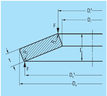
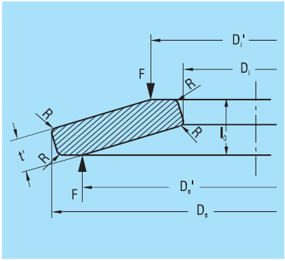
Group 3 - Reduced thickness with contact flats
Increasingly we are called on to provide solutions to larger, bespoke stack requirements. A few terms need introducing. This is covered in more depth on this dedicated Group 3 - reduced thickness disc spring design page.
Contact Flats
We call the contact flat, an annulus, the standard refers to it as a ground surface end, and the SAE HS1582 Spring Design Manual as a Contact Bearing Flat. Some call it the working surface. Whatever you wish to call it, these serve a purpose, namely:
- to improve the definition of the contact point at which the load is applied
- and in stack configurations, to reduce the friction on the guide rod, by adding stability.
Reduced Thickness - t'
Using a contact flat shortens the moment arm. If you introduce a contact flat, the disc spring requires a greater load for the same deflection. For very practical reasons of interchangeability, which means maintaining the free height of a spring, and matching loads as closely as possible, the thickness of the disc spring must be reduced. This is denoted by t' (t dashed).
Disc Spring configurations
Disc springs can be stacked in series, parallel or a combination of the two. This allows for great flexibility in achieving both the working load as well as deflection parameters required for a particular engineered application. Note: the accepted nomenclature depicts values relating to the stack with a capital letter and those to a single disc spring in lower case,
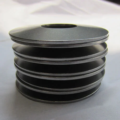
A stack containing 14 disc springs in series i=14
When stacked in Series,
where i is the number of disc springs in series:
- the Total applied Load of the Stack = applied load of a single disc. Fstack = fsingle disc
- the Total Stack Deflection = the Deflection of a single disc multiplied by the number of discs in the stack which translates to: S= i.s which if read aloud is Sstack = i · ssingle .
- similarly, the Unloaded Stack Height = the height of a single disc multiplied by the number of packets in the stack L0 = i. l0 and finally,
A stack containing 16 disc springs made up of 8 packets in series i=8, with two disc springs in parallel n=2, in each packet.
When stacked in parallel
(think of how you would pack spoons neatly in a cutlery draw, each fitting into the next so as to take up less space).
For a single packet of n disc springs in parallel:
- the Total Load of the stack = Load of a single disc multiplied by number of discs n in parallel.
- the Total Deflection of the entire stack = the Deflection of a single disc spring, ie. S = s ,and finally
- the Unloaded Stack Height = height of a single unloaded disc spring plus the total number of discs in parallel n minus 1 multiplied by the thickness t (or t') of a single disc spring ie L0 = l0 + (n-1).t or t'
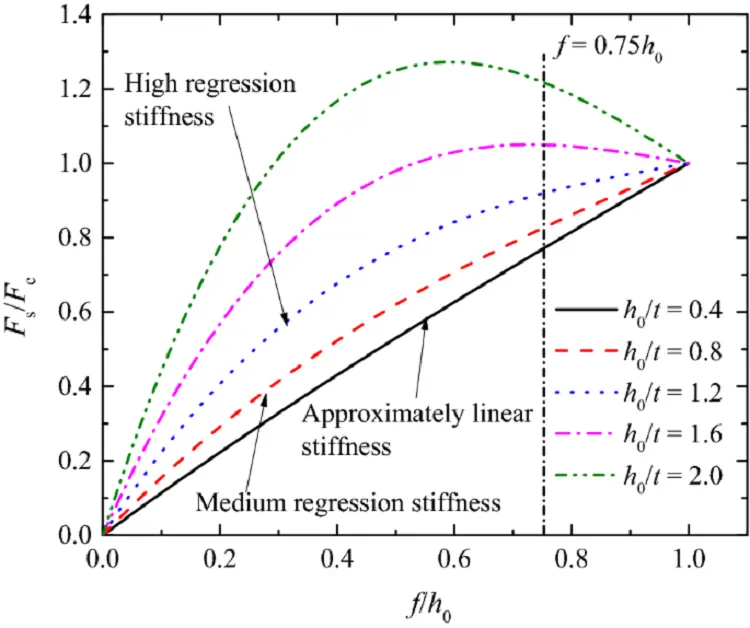
Progressive, Linear & Digressive - Load Curve Response
One might expect that the engineering requirement for a spring stack be that the spring load increases linearly as the load/compression increases, i.e. the rate of the force characteristic remains constant. This need not be so and instead different characteristics can be achieved. We can design the stack so that beyond a certain amount of deflection the force required to further compress the stack increases (progressive), or plateaus off (digressive). These can be achieved through the application of different stack configurations using the principles introduced above.
The key points on disc springs:
- They can be used alone but are most often used in stacks
- They are used to absorb energy or to apply a load
- Their application will have them acting in a either a static or dynamic manner
- When used dynamically we must always consider fatique
- Disc Springs are made from a wide variety of special spring steels and alloys depending on the operating environment conditions:
- Ambient temperature
- Presence of corrosive substances
- Electrical current
- They are through hardened to between Vickers HV 420 and 510 (Rockwell C, HRC 46-52) but this depends on the alloy used
- As important as hardening is the process of tempering
- Electroplating is discouraged, as this may result in the disc springs becoming brittle and failing!
Technical Dimensions - DIN-EN-16983 (DIN 2093)
Although we are principally known for specialising in the larger Group 3 reduced thickness disc springs with contact surfaces (thicknesses of 6mm and greater), we do cater for the smaller sizes, such as these listed below.` all the Relevant Information on Group 3 disc springs is avialable for you download to assess, but don't hesitate to contact us, if you need help.